Local Control Board (LCB)
The Local Control Board (LCB) is an optional device that provides an external interface for the Precision Current Regulator Controller (PCRC) for diagnostic purposes, and tuning of the user's system should that be necessary. See the 'Current Regulator Tuning' section below for more information on Tuning a system.
The LCB connects to the Local Control connector on the PCRC front panel using a standard DB37 M-M cable.
The LCB connects to the Local Control connector on the PCRC front panel using a standard DB37 M-M cable.
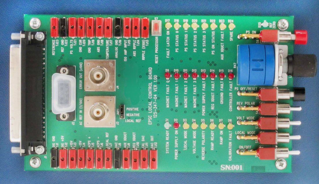
LOCAL CONTROL BOARD 125-347-04
Features
Local Control Functions
S1: ON/OFF, ON/OFF switch for the local control board power, allows the board to be plugged into a powered system while in the OFF position.
S2: LOCAL MODE, Selects LOCAL or REMOTE mode.
S3: VOLTAGE MODE, Selects VOLTAGE mode or CURRENT mode.
S4: REVERSE POLARITY, Allows control of reversing switches.
S5: PS OFF/RESET, Momentary pushbutton to turn the power supply off, reset all interlocks, and clear the fault latch.
S6: PS ON, Momentary pushbutton to turn the power supply on.
S7: RESET PROCESSOR, Momentary pushbutton to reset the internal processor for the control chassis.
R47: LOCAL CONTROL POT, This provides the 0 to +10V local control reference.
LED Functions
In general, yellow LEDs indicate status, red LEDs indicate faults (or ON), and green LEDs indicate ready.
D1 (green): SYSTEM READY, Indicates that all interlocks are OK and the system is ready to be turned on.
D2 (red): POWER SUPPLY ON, The PS enable signal is active requesting the supply to turn on.
D3 (yellow): LOCAL MODE, Indicates the controller is in local mode.
D4 (yellow): VOLTAGE MODE, Indicates that the controller is in VOLTAGE mode.
D5 (yellow): REVERSE POLARITY, Indicates that the reverse polarity line for an external reversing switch is active.
D6 (yellow): RAMP READY, Indicates that a ramp command has been put on hold by the external hold line.
D7 (yellow): RAMP ON, Indicates that the controller is ramping the supply current.
D8 (yellow): CALIBRATION FAULT, Indicates that one or more of the controller calibration loops has reached its limit.
D9 (red): MAGNET FAULT 0, Both the MAGNET FAULT 0 and KLIXON 0 interlocks are faulted.
D10 (red): MAGNET FAULT 1, Both the MAGNET FAULT 1 and KLIXON 1 interlocks are faulted.
D11 (red): MAGNET FAULT 2, MAGNET FAULT 2 interlock is faulted.
D12 (red): MAGNET FAULT 3, MAGNET FAULT 3 interlock is faulted.
D13 (red): POWER SUPPLY FAULT, Indicates that the power supply is not ready.
D14 (red): REGULATED TRANSDUCTOR FAULT, The regulated transductor interlock is faulted.
D15 (red): GROUND CURRENT FAULT, The ground current has exceeded the trip limit.
D16 (red): CONTROLLER FAULT, The controller has detected a serious internal problem.
D17 (yellow): FAULT LATCH ON, Indicates that the 8 fault lines (LEDs D9-D16) are in latched mode. In latched mode, all faults remain until the latch is turned off.
D18-21 (yellow): POWER SUPPLY STATUS 0-3, Optional power supply status bits. These bits have no effect of operation, displayed for diagnostic purposes only.
D22 (yellow): POWER SUPPLY ON STATUS, ON status reported by the power supply.
D23 (yellow): AUXILIARY TRANSDUCTOR FAULT, Indicates that the auxiliary transductor is faulted.
D24 (yellow): SPARE, Spare LED for future use.
D25 (green): REFERENCE ZERO, Indicates that the local reference is set to zero, must be zero to turn the power supply on.
Analog Test Points
TJ1: Digital Ground, use with TJ2 to TJ7.
TJ2: +5V supply, (4.95 to 5.10).
TJ3: +15V analog (+14.50).
TJ4: -15V analog (-14.50).
TJ5: ACPS+ (+15.0V), internal AC-DC power supply positive output.
TJ6: ACPS- (-15.0V), internal AC-DC power supply negative output.
TJ7: Local Reference (0 to +10V), set by the 10 turn pot (R47).
TJ8: DAC ground, use with TJ9 to TJ15.
TJ9: Auxiliary Transductor, +/-10V signal from daughter card.
TJ10: Regulated Transductor, +/-10V signal from daughter card.
TJ11: Cal DAC output, not used on PCRC.
TJ12: DAC Output, internal reference for current regulation.
TJ13: Ripple, AC ripple on regulated transductor amplified by 100.
TJ14: Absolute Ripple, the filtered absolute value of the ripple on the regulated transductor (x100).
TJ15: ISO Amp Input, this is the ground reference input to the isolation amplifier. A 0 to 10V signal produces an isolated 0 to 5V signal for the power supply. For bipolar systems, the range is -10V to +10V (-5V to +5V at the supply).
TJ16: Analog Ground, use for TJ17 to TJ21.
TJ17: Temperature, PCRC internal temperature (10 mV / °F).
TJ18: Absolute Ground Current, the absolute value of the ground current (0-10V at 10mA/V).
TJ19: Ground Trip Point, 2.5V.
TJ20: Ground current, signal before absolute value circuit (-10V to +10V).
TJ21: Power Supply Volts, voltage monitor signal from power supply.
TJ22: Reference Ground, use with TJ23.
TJ23: Reference, (6.75V to 6.90V).
Chassis Configuration (9600 BAUD UART)
The LCB provides a UART interface in a DB9 connector (J2), allows configuration of the motherboard and daughterboard EEPROMs, as well as diagnostic information.
Current Regulator Tuning
In many cases it may not be necessary for the user to tune their system, as the Daughtercard that comes with the PCRC has been calibrated and adjusted before being shipped. Tuning requires removal of daughtercard components and also requires specialized test equipment (a Resistor/Capacitor Decade box, an Oscilloscope, and a Function/Signal generator are required) in order to perform the tuning process. The user should give careful consideration as to whether tuning is necessary or not before attempting the tuning process.
The local control board has two BNC connectors for tuning the error amplifier for the current regulation. The AC input connector (J3) allows a square wave from a signal generator to be added to the local control reference. A differential amplifier subtracts the regulated transductor signal from the local reference, and puts the difference on the error out BNC (J4) for viewing with a scope.
The input signal is divided by 100 to allow a 10 volt signal to be used for a 1% step in output current. The error signal is amplified by 100 to allow small signals to be viewed clearly on a scope.
For a more complete and detailed description of the Daughtercard tuning process, refer to the Daughtercard Tuning Instructions Document below.
- BNC connectors for current loop tuning
- Local control (on-off, output level, interlock reset) of the power supply
- 25 LEDs to indicate status
- 23 Test points for analog voltages
- UART (9600 baud) diagnostic/configuration interface
- Reset switch for the controller chassis processor
Local Control Functions
S1: ON/OFF, ON/OFF switch for the local control board power, allows the board to be plugged into a powered system while in the OFF position.
S2: LOCAL MODE, Selects LOCAL or REMOTE mode.
S3: VOLTAGE MODE, Selects VOLTAGE mode or CURRENT mode.
S4: REVERSE POLARITY, Allows control of reversing switches.
S5: PS OFF/RESET, Momentary pushbutton to turn the power supply off, reset all interlocks, and clear the fault latch.
S6: PS ON, Momentary pushbutton to turn the power supply on.
S7: RESET PROCESSOR, Momentary pushbutton to reset the internal processor for the control chassis.
R47: LOCAL CONTROL POT, This provides the 0 to +10V local control reference.
LED Functions
In general, yellow LEDs indicate status, red LEDs indicate faults (or ON), and green LEDs indicate ready.
D1 (green): SYSTEM READY, Indicates that all interlocks are OK and the system is ready to be turned on.
D2 (red): POWER SUPPLY ON, The PS enable signal is active requesting the supply to turn on.
D3 (yellow): LOCAL MODE, Indicates the controller is in local mode.
D4 (yellow): VOLTAGE MODE, Indicates that the controller is in VOLTAGE mode.
D5 (yellow): REVERSE POLARITY, Indicates that the reverse polarity line for an external reversing switch is active.
D6 (yellow): RAMP READY, Indicates that a ramp command has been put on hold by the external hold line.
D7 (yellow): RAMP ON, Indicates that the controller is ramping the supply current.
D8 (yellow): CALIBRATION FAULT, Indicates that one or more of the controller calibration loops has reached its limit.
D9 (red): MAGNET FAULT 0, Both the MAGNET FAULT 0 and KLIXON 0 interlocks are faulted.
D10 (red): MAGNET FAULT 1, Both the MAGNET FAULT 1 and KLIXON 1 interlocks are faulted.
D11 (red): MAGNET FAULT 2, MAGNET FAULT 2 interlock is faulted.
D12 (red): MAGNET FAULT 3, MAGNET FAULT 3 interlock is faulted.
D13 (red): POWER SUPPLY FAULT, Indicates that the power supply is not ready.
D14 (red): REGULATED TRANSDUCTOR FAULT, The regulated transductor interlock is faulted.
D15 (red): GROUND CURRENT FAULT, The ground current has exceeded the trip limit.
D16 (red): CONTROLLER FAULT, The controller has detected a serious internal problem.
D17 (yellow): FAULT LATCH ON, Indicates that the 8 fault lines (LEDs D9-D16) are in latched mode. In latched mode, all faults remain until the latch is turned off.
D18-21 (yellow): POWER SUPPLY STATUS 0-3, Optional power supply status bits. These bits have no effect of operation, displayed for diagnostic purposes only.
D22 (yellow): POWER SUPPLY ON STATUS, ON status reported by the power supply.
D23 (yellow): AUXILIARY TRANSDUCTOR FAULT, Indicates that the auxiliary transductor is faulted.
D24 (yellow): SPARE, Spare LED for future use.
D25 (green): REFERENCE ZERO, Indicates that the local reference is set to zero, must be zero to turn the power supply on.
Analog Test Points
TJ1: Digital Ground, use with TJ2 to TJ7.
TJ2: +5V supply, (4.95 to 5.10).
TJ3: +15V analog (+14.50).
TJ4: -15V analog (-14.50).
TJ5: ACPS+ (+15.0V), internal AC-DC power supply positive output.
TJ6: ACPS- (-15.0V), internal AC-DC power supply negative output.
TJ7: Local Reference (0 to +10V), set by the 10 turn pot (R47).
TJ8: DAC ground, use with TJ9 to TJ15.
TJ9: Auxiliary Transductor, +/-10V signal from daughter card.
TJ10: Regulated Transductor, +/-10V signal from daughter card.
TJ11: Cal DAC output, not used on PCRC.
TJ12: DAC Output, internal reference for current regulation.
TJ13: Ripple, AC ripple on regulated transductor amplified by 100.
TJ14: Absolute Ripple, the filtered absolute value of the ripple on the regulated transductor (x100).
TJ15: ISO Amp Input, this is the ground reference input to the isolation amplifier. A 0 to 10V signal produces an isolated 0 to 5V signal for the power supply. For bipolar systems, the range is -10V to +10V (-5V to +5V at the supply).
TJ16: Analog Ground, use for TJ17 to TJ21.
TJ17: Temperature, PCRC internal temperature (10 mV / °F).
TJ18: Absolute Ground Current, the absolute value of the ground current (0-10V at 10mA/V).
TJ19: Ground Trip Point, 2.5V.
TJ20: Ground current, signal before absolute value circuit (-10V to +10V).
TJ21: Power Supply Volts, voltage monitor signal from power supply.
TJ22: Reference Ground, use with TJ23.
TJ23: Reference, (6.75V to 6.90V).
Chassis Configuration (9600 BAUD UART)
The LCB provides a UART interface in a DB9 connector (J2), allows configuration of the motherboard and daughterboard EEPROMs, as well as diagnostic information.
Current Regulator Tuning
In many cases it may not be necessary for the user to tune their system, as the Daughtercard that comes with the PCRC has been calibrated and adjusted before being shipped. Tuning requires removal of daughtercard components and also requires specialized test equipment (a Resistor/Capacitor Decade box, an Oscilloscope, and a Function/Signal generator are required) in order to perform the tuning process. The user should give careful consideration as to whether tuning is necessary or not before attempting the tuning process.
The local control board has two BNC connectors for tuning the error amplifier for the current regulation. The AC input connector (J3) allows a square wave from a signal generator to be added to the local control reference. A differential amplifier subtracts the regulated transductor signal from the local reference, and puts the difference on the error out BNC (J4) for viewing with a scope.
The input signal is divided by 100 to allow a 10 volt signal to be used for a 1% step in output current. The error signal is amplified by 100 to allow small signals to be viewed clearly on a scope.
For a more complete and detailed description of the Daughtercard tuning process, refer to the Daughtercard Tuning Instructions Document below.
| daughtercard_tuning_instructions.pdf |
|
|
BiRa Systems welcomes the opportunities to work in collaborations with High Energy Physics Labs and medical cancer treatment centers. We support research and innovation by producing custom hardware and bringing cutting edge technology to new markets.
|