MCOR12 System
|
Features and Advantages
|
General Description
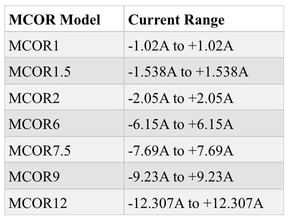
The MCOR12 System is a 16-channel precision magnet driver and is available in 7 different models. Each model of MCOR is capable of providing bipolar output currents in the range from 1amp to 12amps (See table 1 below). The output current can be ramped smoothly through zero. A single, unregulated bulk power supply provides the main DC power for the entire crate containing 16 slots. Each slot may contain one MCOR module of any of the 7 models shown for each of the 16 slots. The entire crate of modules can be controlled by a single EMCOR - Digital MCOR Controller, that resides in slot 00 (the left most slot) of the crate. The EMCOR module contains four DACs, each of which supplies 4 separate output voltages for controlling the 16 available slots with 16 bit resolution. Software is available to control each of the MCOR modules via either a USB or Ethernet interface. If a higher value of bipolar current is required the MCOR30 model is available, which can deliver -30A to +30A.
The MCOR12 System is a 16-channel precision magnet driver and is available in 7 different models. Each model of MCOR is capable of providing bipolar output currents in the range from 1amp to 12amps (See table 1 below). The output current can be ramped smoothly through zero. A single, unregulated bulk power supply provides the main DC power for the entire crate containing 16 slots. Each slot may contain one MCOR module of any of the 7 models shown for each of the 16 slots. The entire crate of modules can be controlled by a single EMCOR - Digital MCOR Controller, that resides in slot 00 (the left most slot) of the crate. The EMCOR module contains four DACs, each of which supplies 4 separate output voltages for controlling the 16 available slots with 16 bit resolution. Software is available to control each of the MCOR modules via either a USB or Ethernet interface. If a higher value of bipolar current is required the MCOR30 model is available, which can deliver -30A to +30A.
|
Table 1
|
Model 2510
|
MCOR12 System Diagram
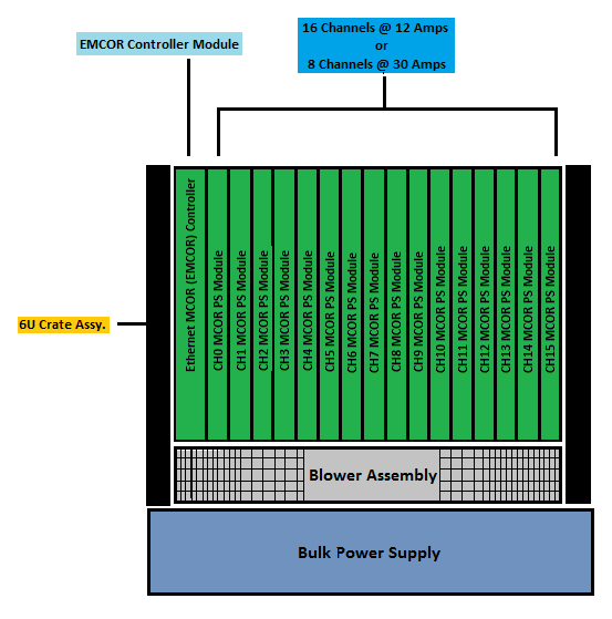
The MCOR System contains one 6U Crate Assembly, up tp 16 MCOR Power Modules, the EMCOR Controller Assembly, A Blower Assembly, and a single Bulk Power Supply.
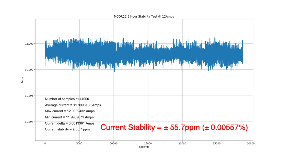
MCOR12 8 Hour Stability Test
Note:
BiRa Systems calculates stability using the absolute maximum and minimum values from the complete set of data. Care should be taken when comparing stability specifications from different manufacturers, as some manufacturers calculate stability using different methods such as full width at half maximum (FWHM). The FWHM calculation will result in a lower stability number and should not be compared directly to the absolute max/min technique. Programming Module (PGM)
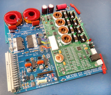
Each magnet design has a unique inductance and frequency characteristic, and in addition each corrector installation has a unique cable plant resistance and maximum current rating. In order to provide “custom tailored” service to each corrector magnet, yet retain a high degree of modularity and consistency in the driver design, each MCOR model power module accommodates a small programming module - PGM. This module contains a set of passive components that match several important characteristics of power module to its corrector magnet. The PGM module shown below is for an MCOR12 module. Each MCOR model type will have its own unique PGM module. 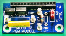
MCOR Crate
The MCOR Model 2513 is a 19” rack mounted 6U x 220 mm crate. The crate has 17 slots: 16 (slot 0 thru 15) for the removable power modules (MCOR12 and MCOR30). Slot 00 (left most slot) houses the EMCOR controller module. The control slot employs two 96-pin VME connectors and the 16 power slots have single 48-pin connectors on the backplane to achieve a modular architecture. The MCOR power modules slide into standard card rails and two locking extractor handles hold each module in place. The power modules are accessed by twisting three 1⁄4 turn captive fasteners and lowering a single hinged clear lexan front cover. The crate's front cover provides safety during operation and a positive air flow for cooling from the separate MCOR Blower Assembly. For more information see MCOR Crate Datasheet. Fault Monitoring
The following conditions will inhibit operation of the MCOR modules as described below:
MCOR 1 and MCOR 2 Bulk Supply inputs are limited by a 3A fuse. All other MCOR models use a 20 amp Bulk Supply input fuse. Fuse blows when input from bulk supply exceeds 3 amps (MCOR 1 and MCOR2) and 20 amps for all other MCOR models. Applications
MCOR12 Technical Specifications
Note that the specifications below assume the EMCOR module as controller and the 2516 current amplifier module is installed on the MCOR module. The 2516 current amplifier is the latest generation amplifier.
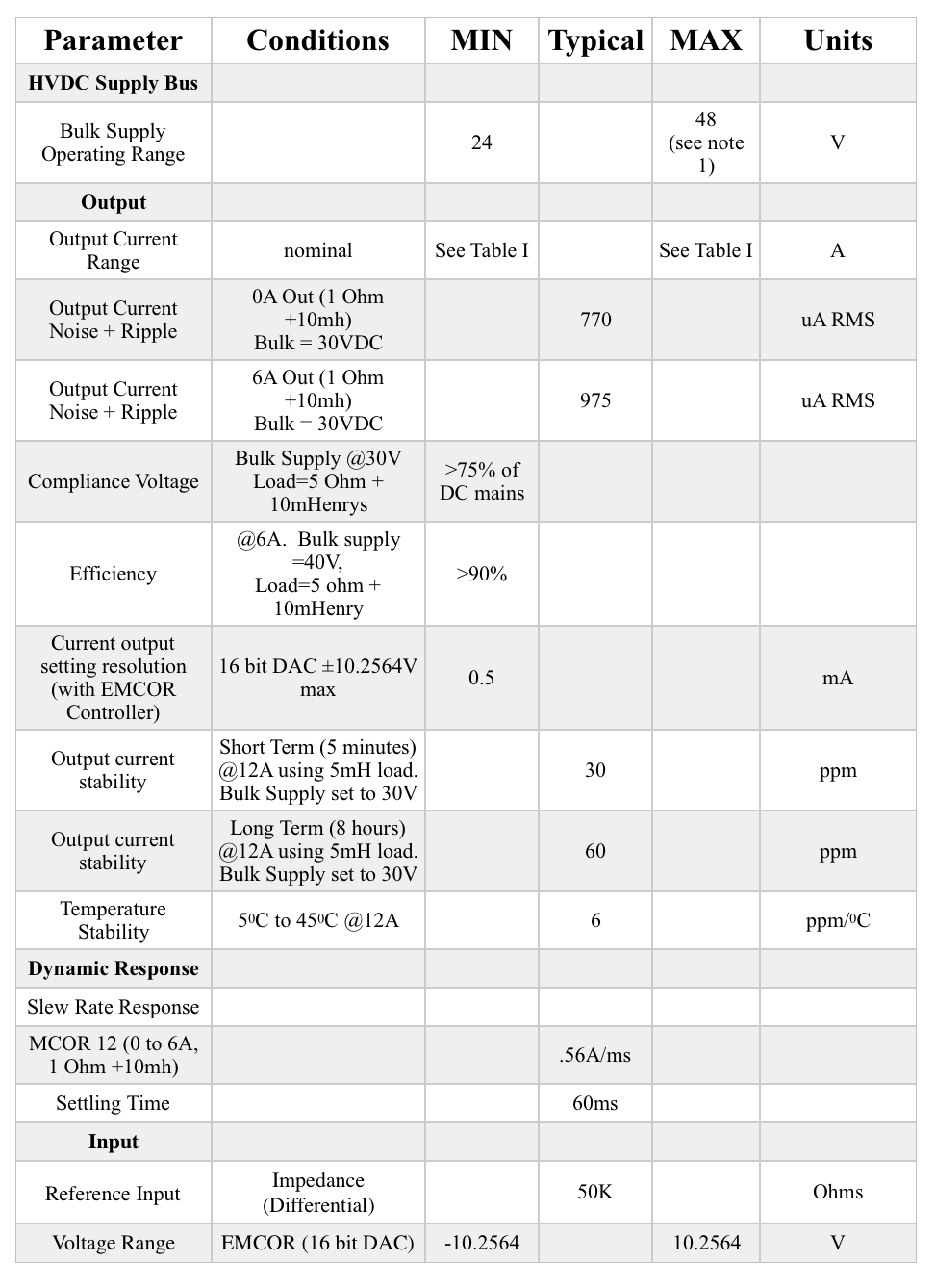
Note 1-High Voltage Option with Higher Bulk Supply Operating Voltage available on request
MCOR12 User Manual
|
| ||
|
|
BiRa Systems welcomes the opportunities to work in collaborations with High Energy Physics Labs and medical cancer treatment centers. We support research and innovation by producing custom hardware and bringing cutting edge technology to new markets.
|